Crank Assembly/Lock-
The early stock crank assembly used a basic nine tooth sprocket to crank
the gear chain and a small modified Craftsman ratchet wrench to manage
cranking the system one direction or another. The wrench also held
the gear in the up position. It had to do this because the rear gear
legs would hit the wing strut before the RLG over center lock would kick
back over center. By shortening the length of the RLG over center
link , and changing the position of the locking pin hole drilled in the
gear tube, the landing gear system will lock in BOTH the up and down position.
Unfortunately I cannot remember exact dimensions. I do not think
the current crop of plans show this correctly, I do remember spending
quite a bit of time working out the geometry to get it right. And
even after I had it built I wasn't confident that the tires would not hit
the wing strut until I had the wings and gear mounted to test it all out
(it is perfect!). I welcome anybody who needs to duplicate dimensions
to visit and take all of the pictures and measurements they need.
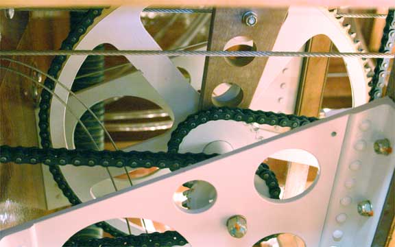
So with the modified
rear locks I basically had a crank that no longer needed the ratchet, and
would simultaneously crank the front and rear gear into a up/locked and
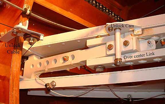
down/locked position. I now only needed to add a unlocking
mechanism. The stock plans show cables going directly to the rear
over center link and pulling on it to unlock it. This will not work
as the unlocking cable will prevent the over center link from moving aft
as the gear is cranked into the up position. This is a ridiculous
drawing, I have a hard time believing that Spence drafted this. The
ONLY place that the cable to unlock the over center link can come from
is one that is approximately equidistant from the link in BOTH the up and
down positions. The only logical place is at the base of the OCL
pivot point at the keel. This IS on some of the old drawings.
From there, some lever needs to be constructed to kick the OCL out of over
center.
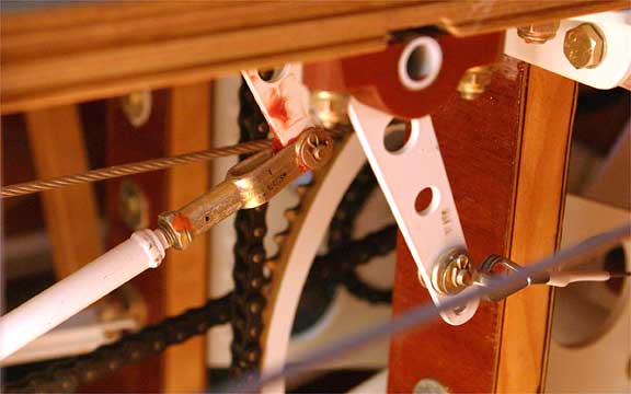
My solution basically
has a unlock handle/lever that pulls a cable that runs to the base of the
over center link arm, and then a cam like lever kicks the over center link
out of "over center" (this last item is well photographed in the
RLG chapter) The same handle/lever is directly connected to the front
landing gear unlocking push pull tube. It took some time to work
out all of the geometry but the system works well. I believe that
this is how Spence "wanted" the system to work.
There is one remaining
missing piece to this puzzle. As my story stands, you would need
two hands, one to pull the unlocking handle and another to crank the gear
while holding the handle in the "unlock" position. The early drawings
solve this by having a small tab that would hold the unlock handle in the
unlock position once you had lifted the handle. You would then proceed
to crank the gear a little bit and then manually release the unlock handle
to a neutral position. If your counting that is four steps 1- lift
unlock handle, 2- crank some, 3- release handle, 4- crank the remainder
of the way. When the ratchet was involved it required even one more
step. God forbid you were in a hurry! I wanted to make this
a two step operation: 1- Unlock gear, 2- Crank.
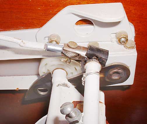
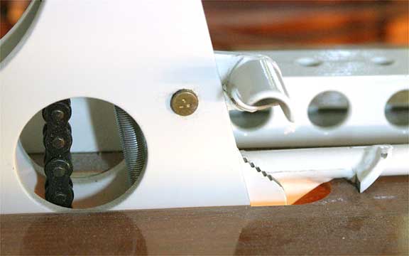
I did this by making
the Unlock handle automatic. Its tough to describe so study the pictures
as well. Basically when you pull then unlocking handle up, a spring
loaded "toothed locking key" engages the handle and holds it up in the
"unlock" position. It remains in that position until the crank handle
swings by and hits a tumbler on the key that swings the "locking teeth"
out of the way allowing the unlock handle to drop free. The timing
of this has to be so that you get a 1/2 swing of the crank before
it frees the unlocking handle, otherwise the system will just jump back
into the locked position. Yes it is a little bit like building a
better mouse trap, but it works elegantly once set up correctly.
I would think that if it were planned out and drafted instead of AdHoc'd
together it would work even better.
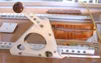
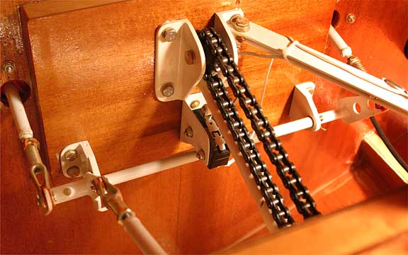
Overall view
|
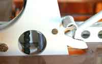
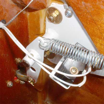
Handle UP, UNLOCK
|
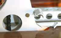
Handle DN, LOCKED
|

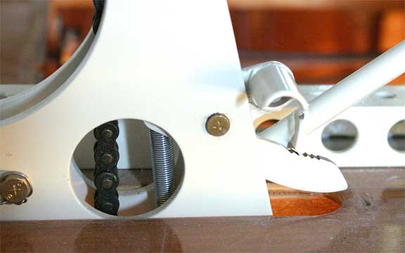
Under deck of Unlock Handle
|
|