Chapter #11, The Wings : Parts
This chapter covers fabricating the basic
parts to build the wings. Included are the ribs, the spars,
the metal fittings, the hinges, the spar end fittings, the fiberglass
leading edge. (See also Chapter #12,
and Chapter #13)
ESTIMATED COST OF WING ASSEMBLY: $6000
TOTAL for EACH wing including everything -This is based on
what was spent over the period of time I was building the wings, it is
an educated guess and seems about right. I did have access to a milling
machine and a lathe to manufacture some of the parts.
MODIFICATIONS: Flap and
Aileron Hinge modifications. The purpose was to get the hinges for
the flaps out of the airstream and make them similar to the Cessna hinges.
The change in the Aileron hinge design was to make them laterally more
stable than those on the plans, and to introduce ball bearings to the hinge.
. A feedback Potentiometer was added to the flap system for the flap
control circuit. I also manufactured my own fiberglass
leading edge in lieu of bending plywood around the front of the wings.
I did this mostly to gain experience with working with glass and vacuum
bagging techniques. It also gave me insight into how difficult it
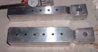
is to do layups on large areas. The rear spar attach plates were
milled to correct for an error in spacing on the car frame (see below). |

|
NOTES ON PLANS: After looking
at many other aircraft, I cannot believe how strong these wings seem to
be built (and how heavy they are in return) The I beams alone seem
like they could handle an aircraft twice the weight. Pay attention
to the routing of the aileron cables during the construction: they have
to be piloted through the float attachment fitting and the flap tube hanger.
I did this in both cases with the careful placement of Phenolic bushings
trying to maintain as straight of a line as possible. This control
cable runs over twelve feet towards the wing centerline so it needed a
few bushings just to support its weight on the long run anyhow.
NOTES ON ASSEMBLY: The parts
that comprise the wing are many and a person could easily consume six months
plus just working on them,
THINGS I WOULD DO DIFFERENTLY NEXT
TIME: I would probably just use the Flap and Aileron hinges as specified
on the plans. The new versions are cool and might give me another
knot of airspeed, but they probably added 200 hours to the aircraft, not
to mention a pound or two: besides Spences design is simpler and I always
prefer simple over complex.
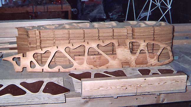
Wing Ribs: I purchased the ribs
used on my aircraft from Al Norman in Monterey. Al had started a
project back "in the day" and I was lucky enough to pick up the ribs
off of him. He also included the two templates that they were used
as router guides. He did not have the ribs for the Flap and Ailerons
cut so I made templates and cut those myself. The wings were cut
on a table saw using a template to insure that they all matched.

Wing Ribs and Cutting Jig
Spars: The Spencer Aircar
Main Spar is an "I" beam with filler blocks added at hinge points and at
the strut attach area. The Rear Spar is a "C" shaped web with one
spruce cap on the top and bottom. I built my spars using 45 degree
bias 1/4" Birch Aircraft grade plywood and Sitka Spruce caps, both purchased
from Aircraft Spruce and Specialty. The plans did not specify the
45 degree plywood but I opted for it because spars are generally recognized
as being stronger using plywood with the grain on the 45 rather than
running parallel to the caps. The tapers in the spar caps were carefully
marked with a marking knife and then the bulk of the material was removed
with a electric planer. I then hand planed the final taper.
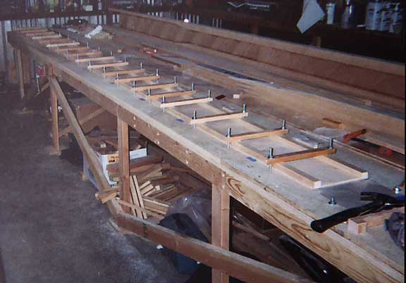
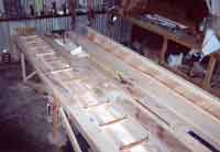
The spars were built flat down on a carefully leveled table. Holes
were drilled in the table every foot or so and small fir cross pieces provided
clamping force via carriage bolts. The caps were kept straight by
blocks that were initially set true by referencing a tightly stretched
75 lb test fishing filament. I glued the caps on one side of the
I beam at a time and then glued filler blocks in one side at a time.
Gluing Caps on Main Spar
|
|
Same, Higher Angle
|
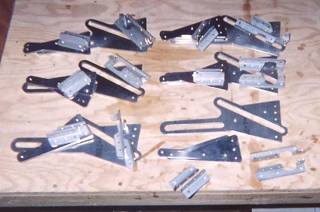
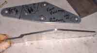
Metal Parts:
Most of these were
made as per the plans using the specs provided. As it is with most
of the assemblies on the Aircar, there are numerous small pieces of aluminum
angle that function as hinge points, pulley assemblies, and brackets.
There are also several welded assemblies including the Bellcranks, and
the flap tube fittings. These can be seen in the photo at the
top of this page. There are a few parts that required the assistance
of a lathe and mill. These included the new flap hinges, the end
fittings for the wing spars, the bushings for the wing attachments, and
the bushings for the flap tube. I was fortunate enough to have access
to
a metal shop - Thanks Brian :-)
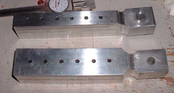
Of Particular Note......
* The upper Strut-end fittings
were pretty straight forward to make, it just takes time to chip away the
aluminum.
* The lower Strut fittings
were a touch trickier. I plotted the fitting in CAD and figured out
where the radius points should be for the required 5 degree sweep that
is built into the fitting. After dropping a 1" mill at the proper
points the billet was rotated and re aligned with the table of the mill.
An easier way to do this is to use a rotary table but I did not have access
to one at the time. The Opposite end of the fitting was left square
to slide into the strut tube for drilling on final assembly. After
it was drilled the extra material was removed from the shank.
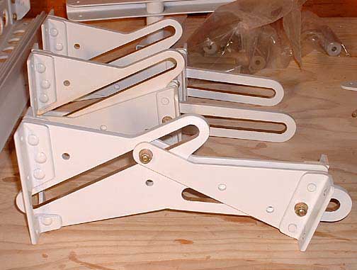
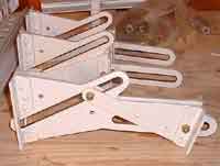
* Flap Hinges - I was
impressed with the "cleanliness" of Jim Bs Flap Hinges. They are
basically a guide plate and two rollers much like the system used on the
Cessnas. I Scanned Jim's Drawings, and Scanned the original Plans
and then redrew everything in AutoCAD. I then milled the plates,
three at a time, on a Bridgeport mill. I am pleased with the
final results but it certainly added quite a bit of time to the project.
It also required modifying the rear wing spar and the flap spar.
The DXF files can be found here: Flap
Arm Flap Track THESE ARE STILL
UNTESTED!

Flap Hinges awaiting assembly
|
Assembled and Painted Hinges
|
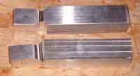
Lower Strut Ends
before Lightening
|
Lower Strut Ends
One is Lightened
|
Offset Rear Spar
Mount Plates
|
Fiberglass Parts
I constructed the leading edge out of
fiberglass, and I also made some "bubbles" to cover the flap hinge protrusions.
The Bubbles were made using a
simple male mold constructed by shaping some balsa, gluing it to plywood,
and glassing it over. It was sanded super smooth ant then well waxed,
Three layers of 4 oz BID were used as the layup, I used plastic wrap
as a simple "one atmosphere vacuum bag". After cure the parts were
popped off and I sanded them smooth.
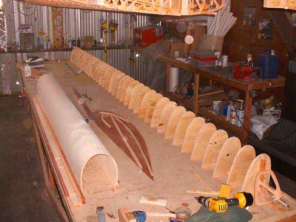
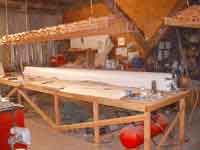
The Leading Edge I first
made a male form using Plywood "shapers" glued aprox 8" apart along a flat
table. The formers had holes drilled in them to allow the vacuum
to work along the full length of the mold. "Wigglewood" plywood was
glued along the top of the formers to produce a male mold. There
was a 1/2" gap left along the bottom of the formers to allow for the vacuum
air to do its thing. The form was cleaned up and irregularities filled
using common drywall compound (its cheap). I then covered the
form with plastic sheeting which acted as a release agent. The layup
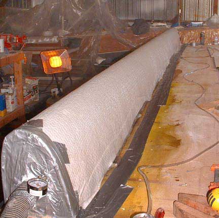
was done using epoxy and five layers of 6 oz BID. This created a
nice strong shell that should handle a few poundings into the occasional
pier. After the layup was done I used dacron as a peel ply on top
and then a breather/bleeder ply. This was covered with a layer of
plastic sheeting and duct tape was used to seal up the envelope as well
as I could. The layup was so large that I had difficulties getting
enough vacuum so I had my pump working at one end, and I attached my shop
vac at the other end. This gave me several inches of vacuum and seemed
to work out well. Next time I will probably try to work on a better
sealing surface for the envelope. All in all the leading edge experiment
worked out well. As usual it took twice as long as I anticipated.
Chapter 13 shows The leading edges being attached to the skinned wing.
They went on easily, and only required minor filling to get the surfaces
to a nice finish.
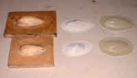
Glass Bubbles:
Mold/Finished part/Rough
Part
|

Building the male form
for the leading edge
|
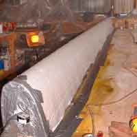
Vacuum Bagging the LE
|
That's a long Vacuum Bag!
|