
Various failed attempts!
|
|
|
|
Various failed attempts!
NOTES ON PLANS: The plans
only show a basic idea for a cover. This is illustrated in one of
the loose change notices. The sketch shows a plate that rotates with
the gear leg and is held on by a few screws. It shows the side of
the hull as perpendicular to the tube. This however is not how the
hull section actually IS. This is a serious gap in the plans as far
as I an concerned. I am sure Spence worked out a solution and perhaps
documented it somehow. But I was not able to chase down any documentation.
The issue with constructing these plates is that as they rotate with the
gear legs they are subject to the changing angle that is formed by the
relationship of the side of the hull and the bottom of the spring gear
leg. This angle gets smaller as the gear leg goes down because the
side of the hull is angled at this point and not perpendicular to the gear
tube. This angle acts like a pair of scissors and the gear leg pinches
the gear cover as the legs go down. This is aggravated by the fact
that the hull side is angled upwards at this station. The net effect
is that the gear legs and hull side want to crush what ever plate is covering
the hole. I have seen several recent Aircars that appear to have
solved this by simply not putting any kind of cover over the hole.
I may end up doing the same if my covers don't work out in flight as well
as they do in static tests on the ground.
NOTES ON ASSEMBLY: Maybe
I was just being dense but I really struggled with these. The movement
of the cover in relation to the gear leg is fairly complex with no easy
hinge point or center of rotation as the leg rotates. I tried several
different approaches including making some plates out of Acrylic so I could
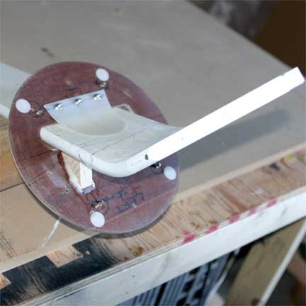
see what was going on inside. The "eureka" came when I decided to
just hot glue the cover to the gear leg while in the down position and
remove it intact from the hull. This allowed me to view the operation
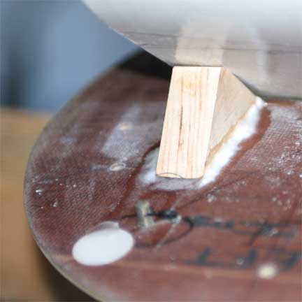
from the "inside out". The solution turned out to be adding a "kicker"
block to the inside surface of the plate that helps kick the plate around
during those last few degrees of rotation where it had been previously
binding between the gear leg and side of the hull.
THINGS I WOULD DO DIFFERENTLY NEXT
TIME: Call Dale Anderson and see if he remembers how he and Spence
solved the puzzle
 |
 |
 |
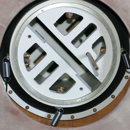 |
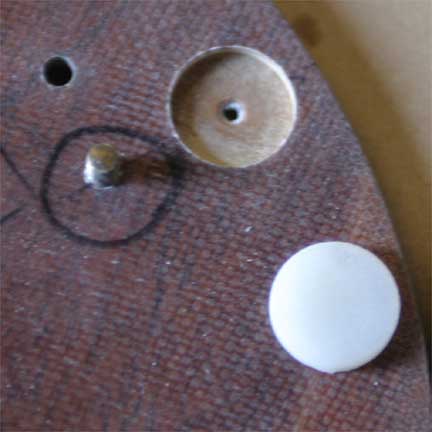
These next shots show the cover. The nylon pucks act as a bearing surface for the plate. Also visible is the "kicker block" that helps push the plate around during that last 10 degrees of rotation where it was binding. The plate is held on using springs that are attached to the bolts on the outer ring of the Gear Tube. The springs hold the plate against the hull. They are attached to the cover plate by screws that have been modified to have a "hook" (sorry no picture yet). I attach the springs using a custom made tool that pulls the spring into position and deposits the loop of the spring onto the screw. The nylon "flap" that appears to cover the hole helps push the plate downward.
 |
 |
 |
 |
 |
Next Up: Landing Gear Mechanisms
|
|
|
|