|
|
|
|
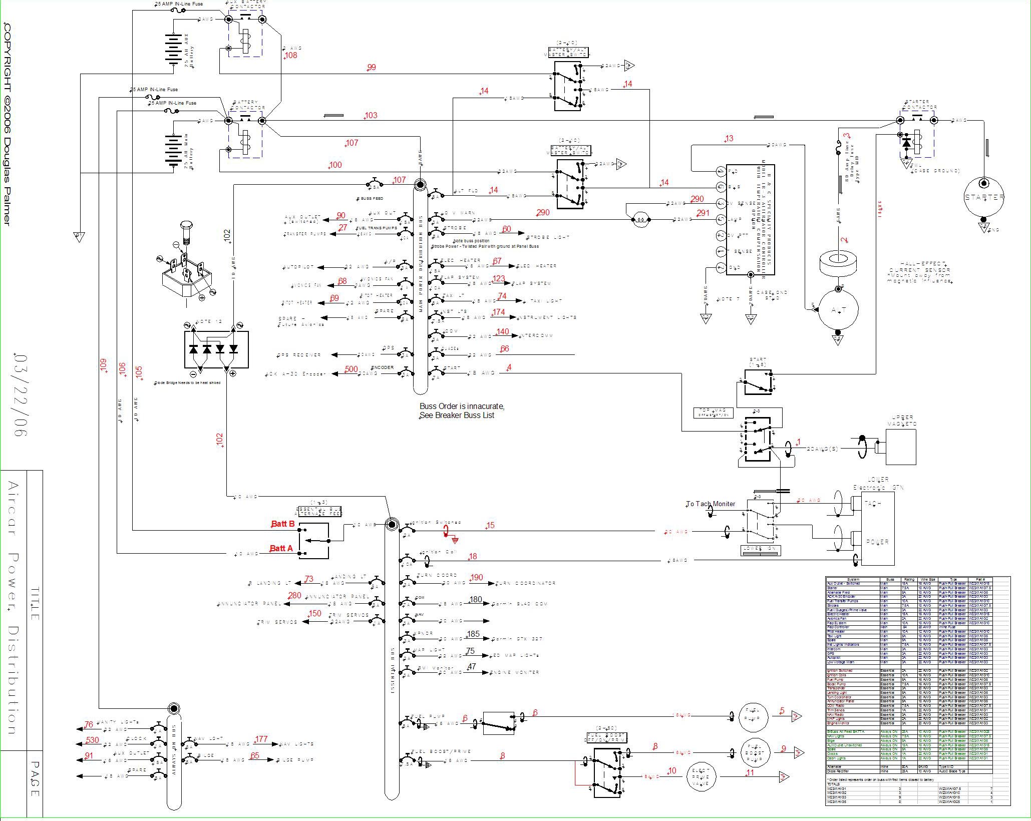
Electrical System Design: Aircraft Electrical system design is a subject that could easily fill a college level course textbook and then some. Way back when I had to start closing the tail and wings I needed some minimal idea of at how to select the proper size wires. This turns out to be something of an inexact science that factors in voltage drop, usage, temperature increases in single wire and bundled wires, etc. Like most other things I bought a few books and dove into the task. Most of the books go way into theory and the history of the systems found on aircraft. The best resource from the home builders point of view has to be Bob Knuckles AeroElectric Connection Book. While his book is definitely a little long-winded it is an excellent resource for systems design. Bobs basic theory is that the system, at some point IS going to fail, and that the design should be ready for this failure and still be able to get the aircraft safely on the ground. This philosophy becomes especially valid in a modern electrically based project. After combing over Bobs materials and the included schematics I came up with my own system. Basically mine is a two battery, one alternator system with three busses: a main buss, essential buss and always on buss. The two batteries will allow me to park the aircraft in the water with the nav lights on and the bilge pump on "auto" and still have at least one fresh battery in the morning. It will also allow extra cranking power on cold mornings, or the option to run the electric cabin heater to warm the cabin up before climbing in on cold mornings. I did not go "all the way" and put a second alternator in but the system is designed to easily accommodate this down the road if I go with an all electric panel.
My approach- I
started my attack by running all of the wire bundles first. The wires
are run in bundles relating to their systems with each of the wires labeled
at both ends with a Brother P-Touch labeler then sealing the label to the
wire with clear shrink tubing. As the bundles are created,
they are combed out, and then I have carefully tied them with nylon lacing
cord- I hate the zip ties cause they rip up my hands. OK there are
some zip ties here and there, and they are very useful as TEMPORARY wire
ties. As each system, or branch of wires is done being routed to
the panel area with plenty of extra length, I pull the bundle back out
and spool it up out of the way until I am ready to connect that system.
My goal was to avoid having 500+ wires coming out of the front of the panel
all at once, complete mayhem as I try to sort through each system and wire
it together.
Its important to note
that I am trying to be careful to keep the big, inductive wires away from
the little wires. I am generally running the noise making wires on
the right side of the plane and the communications and smaller wires on
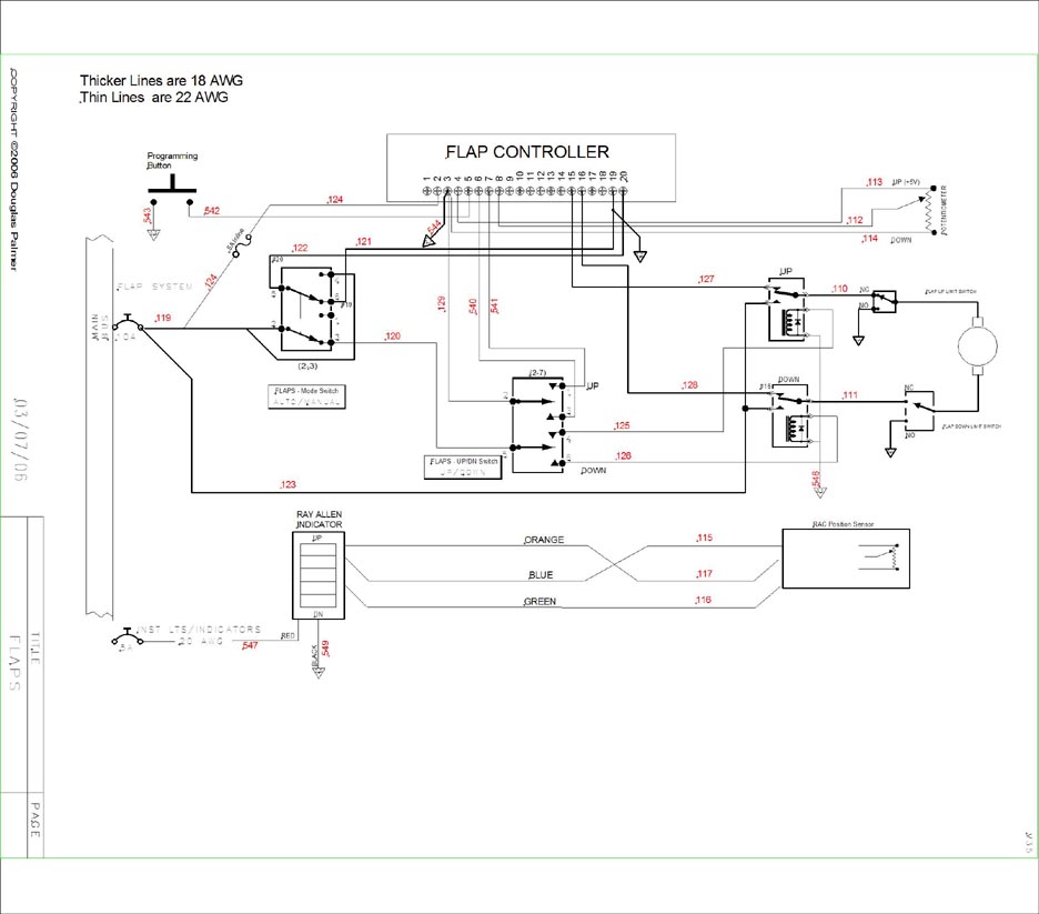
the left side. This for instance keeps things like the flap motor
in one bundle which is separate from the bundle that carries the intercom
wiring.
Basics- A quick note on some basics. I am using the latest Mil-Spec tefzel wire. Most of the connections are terminated one of five ways: with PIDG style slip-on terminals, ring terminals, Knife terminals, Molex connectors, or soldered. For terminals I have found that it is important to buy the quality AMP products as the cheaper brands just don't have as much metal in them and don't hold as well. It also helps a lot to have quality crimping tools, in fact it is essential so don't skimp. For any soldered joint it is important to have a good soldering iron, quality solder, and to not over solder the joint. you want the solder to attach the wires at the end but NOT to wick up into the wire more than necessary. Heat Shrink material also helps reinforce the solder joints.
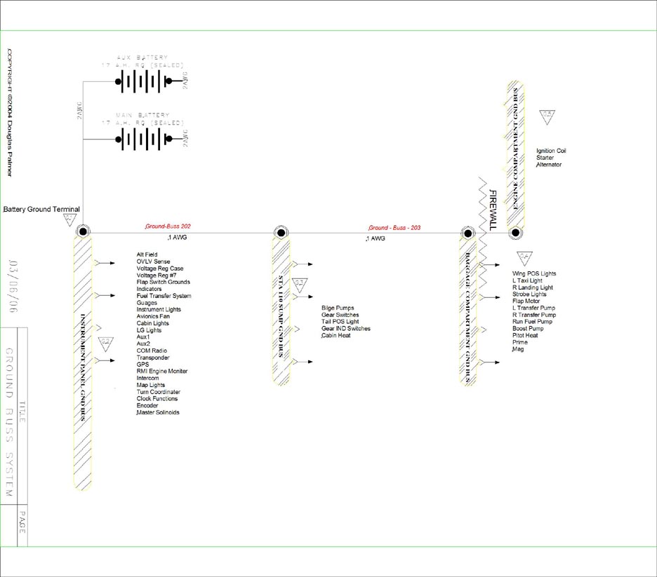
Busses- I separated the electrical
needs into three separate busses: the main buss, the essential buss,
and the "always-on buss".
Main- It was actually kind of hard deciding
what to put on the essential buss, I ended up with the radios on it but
not the flaps, I cut the lights down to just the map and landing lights.
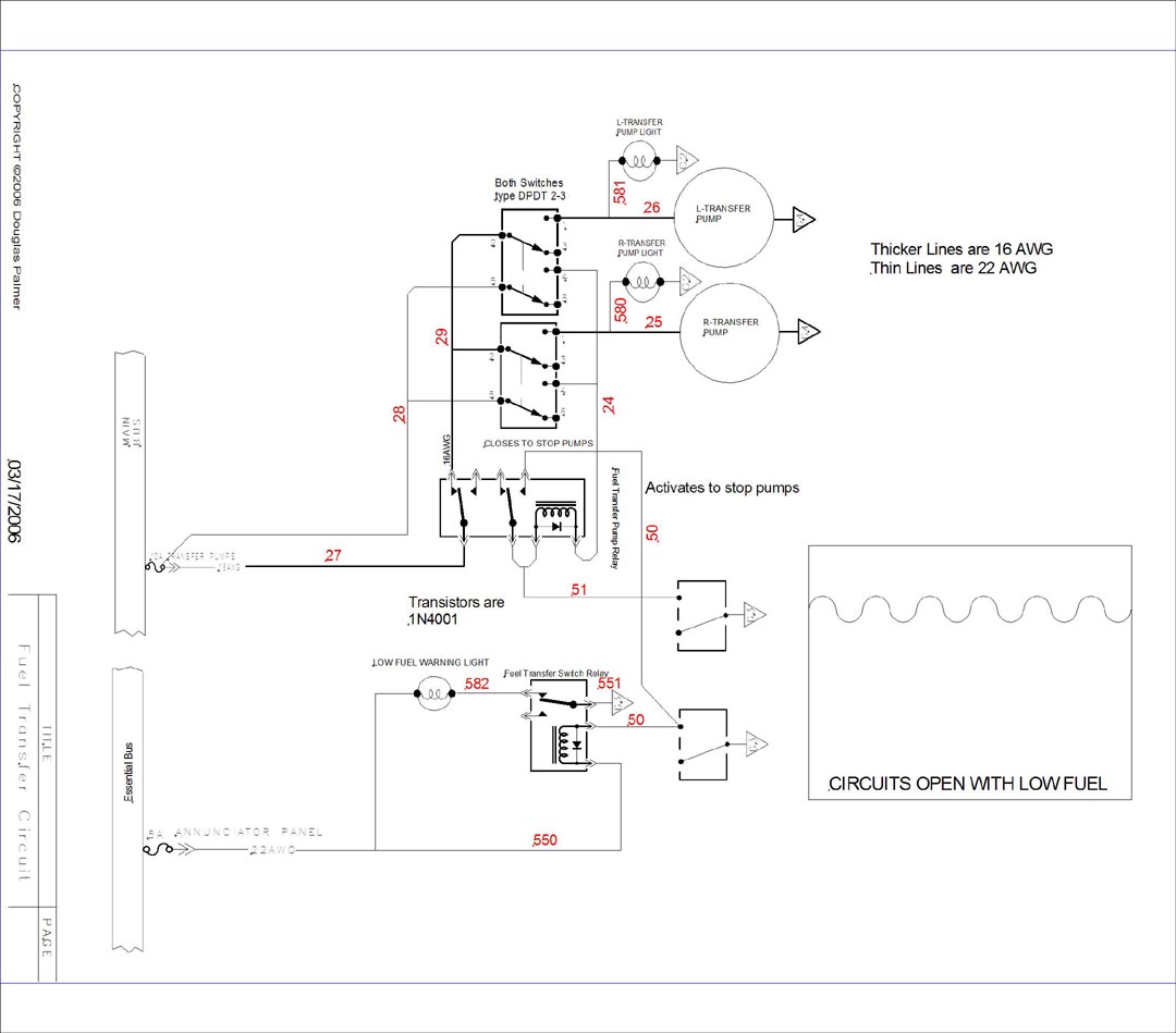
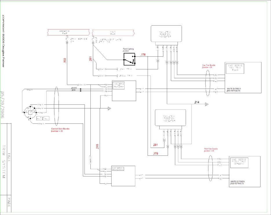
The fuel pumps and engine ignition are on the essential, trim servos but
not indicators. Truth is I still look at what I ended up doing and
can make arguments to move things around still now but I think only time
will tell the wisdom of my plan. For the most part the radios were
left on the essential buss because they can be individually turned off
at the panel. I can land without flaps so I left the flap system
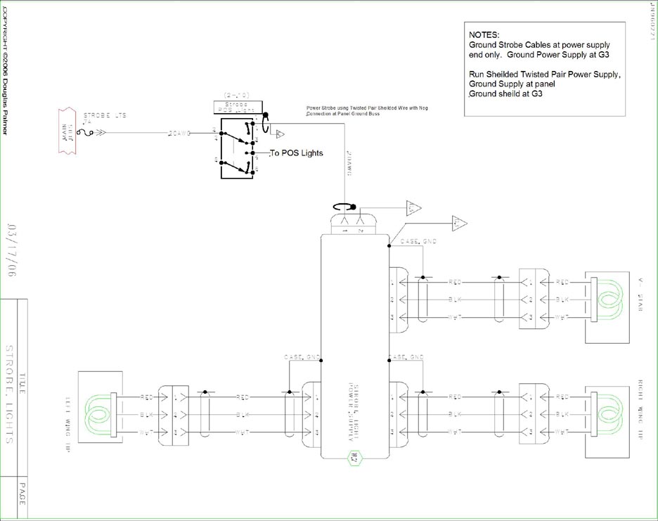
off of the essential buss. For the lights I decided I could function
with only the two map lights and a landing light.
Always ON- I included the cabin
vanity light, clock functions, Nav lights, Bilge pump, and an AUX outlet.
The Nav lights were included so they could be used as anchor lights.
If I was to drop anchor for the night someplace, with the two batteries
I could leave the nav lights on and the bilge pump on. I am currently
trying to find a LED replacement for the high-draw bulbs in the Whelen
NAV lights so I don't have to run the battery all the way down overnight
on the water.
The main buss contains all the items
not on the other two.
Charging system/Batteries- Two batteries
are wired in parallel to two individual contactors which feed the three
busses. The batteries can be used individually or in unison.
The Alternator is a Marine Balcar 80 AMP model. It is externally
regulated, has dual fans and oversized bearings. Its intended design
is for use in a salt water environment. The alternator is controlled
by a B&C Specialty LR-3 Linear regulator with over voltage protection.
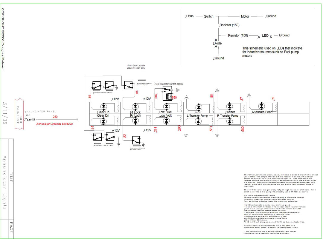
For redundancy, there
is a fused secondary path from each battery to a switch that directly feeds
the essential buss. This switch is located on the lower panel, and
has its own annuciator light. Basically this has created three separate
paths to the essential buss.
|
|
|
|
|
|
|
|
|
|
|
|
|
|
|
|
|
|
|
|
|
|
|
|
|
|
|
|
|
|
|
|
|
|
|
|
|
|
|
|