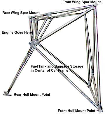
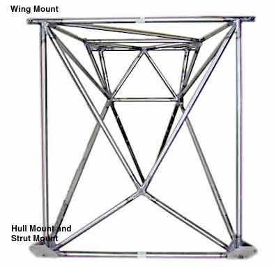
HOME
ARCHIVES
OTHER AIRCARS

Chapter #3 Car Frame Construction


Car frame Front View
   This assembly is displayed as if looking towards the rear of the aircraft.  Visible at the bottom are the two mount points which attach to the wooden hull near the rear landing gear bearing plates.  The wing struts also mount at these plates.  Visible at the top are the mount points for the front wing spars.
Car Frame Side View
This view of the car frame shows the wing mount points at the top of the image, as well as forward hull mounting points at bottom.  The rearward mount will eventually couple with aluminum angle attachments  just above and aft of the step.  The engine will mount and hang off of the rear top section of the car frame.  The fuel tank goes in the center of the structure.  Spence did a good job of  keeping the bulk of the weight centralized and close to the center of lift.

ESTIMATED TIME TO FABRICATE: 150 Hours.
ESTIMATED COST OF ASSEMBLY:
MODIFICATIONS: None, Built to plans
NOTES ON PLANS:  I fabricated my car frame according to the most recent set of plans.  The older version of the car frame has small tubes (4") at 45 degree angles in the upper corners of the front primary structure.  The newer plans do not but have heavier tubing throughout the assembly.  I found a  a discrepancy between the plans for the car frame and the those for the wings.  The spacing between spar mount tubes (and their associated bushings) is listed differently for each assembly.  I built my car frame to the new plans specs, within 1/16" , but as I am currently building my wings, I have discovered that the tubes for the spars are too close together ( aprox. 1/4").  I have spoken with other builders whom are using the factory car frame and they have told me that the spacing is correct on frames out of the factory.  My advice to anyone building their own car frame would be to either: carefully figure out the spacing with the wings set at the S-12-E spec'd  5 degrees of sweep,  use the factory jig to build your frame,  or build the wings and hull first and then make your frames jig fit your final dimensions.  I am solving my spacing issue by milling an offset in to the rear-spar mount plates out of a thicker stock.
NOTES ON ASSEMBLY : CUTTING TUBES: I used the "Ole Joint Jigger" to cut the notches in the tubes. The trick is to use high quality hole saws, cut at a slow speed, and use a cutting oil.  For HOLESAWS I found the Lennox brand to be better than the Milwalkees.  Some hole saws will take a homemade edge after their teeth have all broken off.  I was able to use a dremel cut off wheel to make small teeth that actually cut better than the original hole saws teeth which tended to hang up on the edge of the tubing once the cut was half way through the tube.  The assembly was TIG WELDED and then taken to a heat treating facility to stress relieve it after doing a dye test to double check for cracks.  It was also powder coated.
THINGS I WOULD DO DIFFERENTLY NEXT TIME:  Other than jigging the frame to accurately fit the wings?  I would try to set up the frame as a single airtight unit much like the aerobatic airframes are made.  It could then be pressurized and have a gauge on it to indicate a loss of pressure, meaning that a crack had occurred.

The first part of the car frame assembly can be seen jigged up to the work surface
First assembly is welded and I am starting to jig the secondary assembly on the top part of it (bottom of the image).  I used plumb-bobs, levels and a transit to get everything lined up
The assembly is fully welded and fitted it to the bulkhead Station assemblies  # 110 & # 129

HOME
ARCHIVES
OTHER AIRCARS